The process was actually really easy. The new display has a 1-1 pin layout. No additional pull-up or down wires or resistors were required.
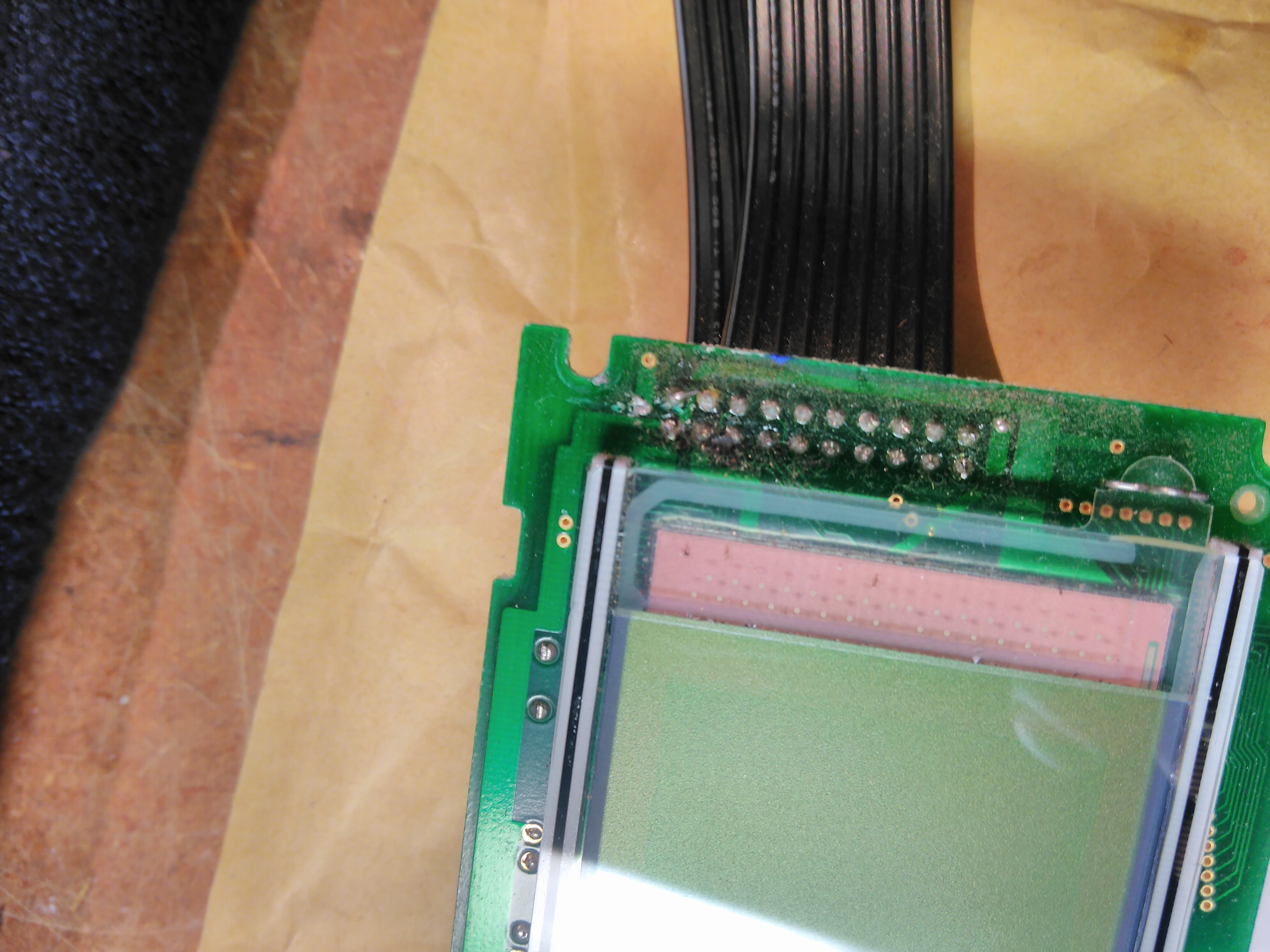
using a desoldering tool to remove the tin from the pinalmost done..
I desoldered the ribbon connector from the old display, and resolderded it onto the new display.
On the backlight driver board, I desoldered the Q1 driver transistor and transformer. The supply voltage to the backlight driver board is an odd 7V. I decided to use an 100Ohm resistor in series. At 80mA the drop voltage will be around 4V, leaving 3V for the LED backlight.
I shorted the VCC to a (former) transformer pin, from which the resistor guides the current to the backlight LED.
The contrast was quite a bit of after replacement, but the range in the menu is quite large, so dialing it down from +14 to -20 did the trick.
end result
On the pictures the image looks white on blue, but it actually is white on black. I’m very happy with the result!
Next one in line to receive the much deserved LCD display upgrade is my Roland D70. As with most others I’ve previously overhauled, this synth has the ‘standard’ 240×64 dot-matrix graphics LCD black-on-green display with EL-foil, which ofcourse is failing after being 25+ years of age.
The new display is pin-compatible with the orignal display. Even the font select pin is already pulled up to Vdd, which mostly is not the case 🙂 The contrast control circuit provides large enough range for the new display. The flatcables may be resoldered to the new display.
Care must be taken to desolder the flatcable from the original display, as the metal wires break easily. I ended up having to cut and strip a a small piece of both flatcables.
As the new display is somewhat thicker, it will push the window rather far out when mounted in the original way. A solution is to mount the display ‘behind’ the mounts, see below picture. I added a few plastic washers to rise the mount off the PCB a little bit, else the LCD unit would be very close to the the larger PCB.
As the space between the LCD and PCB is still very tight, I covered the back of the LCD unit with electrical tape so nothing will short out if the boards touch each other.
Earlier this year I did some work on my Kawai K5, including (ofcourse) replacement of the LCD display with a new white-on-black(ish) LED backlight type. Additionally updated the firmware ROM to the latest version, and I cleaned all the tactile buttons which became almost non-responsive.
Display
The old display had an EL-foil backlight which was barely emitting light, just like all synths with the 240×64 dot matrix display from that era.
I bought a couple of 240×64 displays white on black with LED backlight (from the polish company artronic, but similar to the Newhaven’s white on blue which seem to be popular) which are pin-compatible with the original display.
The flat cable is to be desoldered from the old display, and soldered onto the new display.
One addition needs to be made: Font Select pin needs to be pulled up to VDD, this is done using a small wire soldered directly on the display board between pin’s 19 and 3. On the PSU board the inverter can be desolderded, and replaced by a 100-Ohm resistor (between pins IN and OUT). See schematic below:
snippet of Kawai K5 PSU schematic
The contrast-control gives a large enough range for the new display, so no modifications in resistor values needed here! See below the result:
Buttons
Now the synth is opened up, we can take a look at the tactile buttons. You need to press pretty hard to get some response. To clean them, you need to take them apart.
With long pliers you gently pull the inner part out of the switch.
Inside the casing you will find small copper discs. These need to be taken out.
By soaking a q-tip in alcohol, and pushing it in the casing, you can pull the disc out.
Placing them a piece of foam, you can thoroughly clean the ‘hollow’ side of the dish. Also you need to thoroughly clean the small metal contacts inside of the plastic casing.
This way I’ve cleaned all buttons, and the results are remarkable! Buttons all became very responsive, as new! (Presumably, as I have never owned a brand new K5 🙂 )
Firmware upgrade
As I do with all my synths which I open up, I check if they are running the latest (available) firmware, and if not.. I replace the ROM with a freshly burned EEPROM. I purchased a couple of cheap 27SF512 DIP-28 package EEPROM’s of ebay, which are roughly pin-compatible with the original 27C512, and.. most importantly: programmable using an EEPROM programmer 🙂
The latest 1.3 firmware can be found on the K5synth file section on yahoo groups.
TODO: Output modification
The last upgrade/fix I was planning to perform was an output modification to lift the output level further above noise-floor, an issue which is inherent to the K5.
The mod consists of replacing R33, R34, R35, R36, R37, R38, R39, R40 by 15kOhm-resistors.
In my endeavor to replace and upgrade my synths failing displays with more modern counterparts I decided to replace the 1×16 character LCD, EL backlight (and whining inverter) with a nice white OLED display.
I purchased the display through Comet, a european (Bulgarian to be precise) company. It is clamed the OLED display is HD44780 compatible, on which the original Sharp display is based.. and as most of the character LCD’s are. For reference, see the datasheet of the original Sharp LM16155 display, and the new Winstar OLED display. Here a sheet with additional data for the OLED controller.
I desoldered the flatcable connector from the original display and soldered it onto the OLED display. The contrast pin is unused, and the backlight pins are missing, but apart from this the new display is indeed pin compatible with the original one. But.. as you can see, only the first 8 characters are visible. After some reading and searching I learned about the various adressing modes these displays have.
It seems the original Sharp display is not addressed as a 1 line with 16 character, but as a 2 lines of 8 characters display, being the first line the first 8, and the bottom line the second eight characters. Line 1 starts at address 0h, line 2 at 40h. Below tables from the datasheets show the difference more clearly:
HD44780 addressing
Winstar OLED addressing
I was hoping the Winstar controller would be able to support this ‘older’ addressing mode, by setting a jumper.. or something.
I did find the display would accept a ‘number of lines displayed’ setting in the Function Set setup command. I made a small test-setup using an Arduino controlling the display, so I could experiment with different setup commands and addressing modes. Setting N to 0 or 1 did however not influence the addressing mode. All characters written from address 40h are not visible. No way will this OLED 1×16 display be a direct replacement for a legacy HD44780 based 1×16 LCD display, without altering the way the display is controlled.
The only way to do this is to hack hack the Juno’s firmware, which is not the road I wanted to go down. I do have some microcontroller assembly programming experience, but there was no source available of the Juno’s software, I never disassembled existing binaries like this, and also I did not own an eeprom programmer.
I did however find a binary available from a guy who performs firmware hacks on the JUNO and other synths. After fiddling around with 8051 (which is the Juno’s CPU) tools like dis51, d52 and the as31 assembler I was able to create an readable asm file, and assemble it back to a bin file which was the same as the original bin. This gave me confidence to give it a try.
I purchased a nice cheap Chinese EEPROM programmer (thanks to Dave’s excellent review on EEVblog), and a couple of EEPROM’s of ebay. The original EPROM is a 128kbit NEC D27128D. The EEPROM’s I purchased were Winbond W27E257, which are pin compatible with the NEC’s. Being EEPROM’s, they’re easy to reprogram, which I expected to be doing a lot in the process of testing changes made in the software. The Winbond’s have a capacity of 256kbit, which were the smallest I could find being pin-compatible and in DIP-28-pin package. The software then has to be uploaded in the upper 128kbit of the Winbond EEPROM, from 4000h, to be addressable for the Juno’s CPU.
I spend a lot of time finding the pieces of code where data was written to the display. Below is a subroutine which was easy to find, and also easy to alter. Setting address 0 (first character on first line) is writing 80h to the display, address 40h (first character, second line equivalent to 9th character on 1×16 display) is writing 0Ch. Cutout from the Winstar sheet:
In stead of jumping the 40h in addressing we only jump 8h.
writeLCD_16_chars_17BC:
        MOV A, #80h
        ACALL writeLCD_8chars_DPTR_17AD
        ACALL delay_3_R0to0_17A6
;       MOV A, #0C0h            ; Go to second row of 8 characters
        MOV A, #88h
        ACALL writeLCD_8chars_DPTR_17AD
        ACALL delay_3_R0to0_17A6
        RET
Unfortunately there are a LOT of pieces of code scattered all over the place which all write data to the display, and the jumps of 40h are not always very obvious. To make things even more complicated, there is some shifting going on: When pressing the ‘Write’ button the existing text is ‘shifted’ away and new text is written on addresses 88h and 0C8h respectively. Text will shift ‘home’ when the Write button is released, and original text will re-appear. To make this work with the new OLED addressing this shifting code had to be altered so it doesn’t shifts two lines by 8, but 1 by 16.
After a couple of nights of tinkering I’ve gotten all display output correct. I’m not going to bore you with more details, but feel free to drop me a line if you’re interested.. or wish to view my annotated assembly code. See attached to final .bin file. I can burn the EEPROM for you if you want.
In the the final step I desoldered the electronics from the PSU board used to power the EL backlight. No more whining, and the result is simply beautiful!
One remark: the output of dis51 won’t assemble straight away in as31, it requires some syntax fixup. I hacked dis51 so it does produce direct usable output, and made it include the pointer address in the labels it produces. I can share this if you want.
–UPDATE–
sorry for my late response, at popular request I’ve uploaded the binary and (annoted) assembly file:
This week I started a project in which I want to replace the LCD screens in some of my synths. Most of them suffer from the well known decaying Electroluminescence (EL) backlight problem, resulting in a barely visible screen, and a annoying high-pitched sound from the transformer powering the backlight.
I decided to start with the Wavestation A/D. It contains a 240×64 pixels dot matrix display with T6963 compatible controller. This type of display is used in A LOT of synths from that era. There are some equivalent LED-backlit displays available from various (Chinese) vendors. A lot of people replacing their displays use the white-on-blue version, which looks really awesome. After some searching I decided to go with a white on black display, available from ARTRONIC (http://www.artronic.eu/pl/p/LCD-AG-240064A-DIW-WKK-E6/1035). I find that it better matches the faceplates of most synths, (white on black), and it less bright in the studio without trading in readability.
I used this guide (http://www.tellun.com/wavestation/wavestation.html) as a starting point. I did however want to cut as little cables and add additional components as possible. First I desoldered the flatcable PCB connector from the old Optrex display and re-soldered it to the new LED display. Using an external power supply i powered the backlight LED as a test. The pinouts of both displays were identical so I was pretty convinced the new display wouldn’t burn out. Powering the unit on I found the contrast signal range was way too high (as mentioned in the tellun.com guide), and the font size was off (also mentioned in the guide, suggesting Pin 19 / font selection should be actively pulled high). The latter I find strange as the original Optrex display also has font selection on Pin 19. The pin is open on the mainboard, maybe it is internally pulled high on the Optrex. I bridged pin 3 (+5V) and 19 on the display.
Next issue is contrast. The tellun guide suggest adding an additional resistors as a voltage divider to lower the contrast control voltage range. Doing a little reverse-engineering on the contrast control of the Wavestation reveals it is build around a potentiometer and two resistors (VR1, R2 and R3), a sort of voltage divider fed by -12V. Sort of, because there is no connection to ground, making it just a variable resistor in the range of 0,7k to 2k5 between the LCD contrast pin and the -12V rail.
I found that (while adding additional resistors in series) a resistance of 3.6kOhm gives ideal contrast. So ideally the contrast control circuit should work in the range of 2k5 and 4k5. I determined (using some obscure math) values of 6k8 and 3k9 for resp the resistors R2 and R3 give me approximately this range. While most of the electronics on the mainboard are surface mount, the contrast control is located on the front-panel PCB which is fully through-hole. So, replacing the resistors is an easy job and voids the need of cutting a wire or adding resistors to the display.
All whats left to do is remove the transformer feeding the EL backlight on the old Optrex display, to eliminate the high pitched noise. I reused the wires from the EL feed to power the LED backlight from the mainboard, adding a 100 Ohm resistor from the +5V rail, as described in tellun’s guide.
Et voila:
Excellent result with little costs and a few minor alterations. All steps I performed summarized:
make photo’s of the screws mounting components and boards, these will be useful when screwing everything back together 🙂
desolder 20-pin ribbon cable PCB connector and EL backlight power leads from old Optrex display
solder them back on the new display
connect connector pin 19 to pin 3 on the display
remove the front PCB, and desolder resistors R2 and R3
replace resitors R2 and R3 with new resitors valued 3k9 and 6k8
remove mainboard and desolder the EL transformer TR1
solder an 100Ohm resistor from the + lead of C49 to the pin feeding the EL backlight (see http://www.tellun.com/wavestation/WS_R3.jpg)
replace the battery if possible 🙂
put everything together and close the unit up
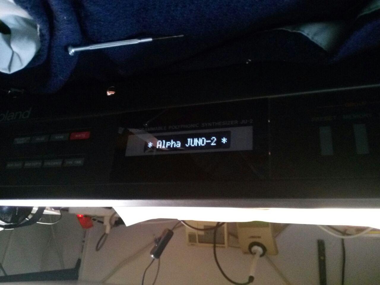
I have a Kurzweil K2000R, Kawai K5, Korg 01/W, Yamaha TG/77 and a Roland D70 which all have the same type of (failing) 240×64 display, wating for a overhaul 🙂 The D70 is in the worst shape with the annoying whine audible in the output signal.. so I´ll think this one will be next in line. Also I have an alpha Juno-2 with an 1×16 charachter LCD displayfor which I found a really nice OLED replacement 🙂 Stay tuned for the report on these!
Last night I watched the movie ‘Fifth Element’ from Luc Besson again. This movie has a great soundtrack by Eric Serra, espacially the track ‘Little Light of Love’. Watch/listen it here: http://www.youtube.com/watch?v=k5PFsP-Bux4
So we can conclude Peter Gabriel and Thomas Dolby didn’t have any involvement in this track. It is a track produced and performed by Erric Serra himself (credited as R.X.R.A.. which is ‘Eric Serra’ phoneticallt). It seems someone (hunkydorey2) had a bunch of tracks, among which ‘little light of love’ assuming it must be Peter Gabriel´s voice and put it ip for download in the early years of internet. Since then it has gone viral. Anyone who has more insight on this perhaps?
At a remote location I have a Foundry Bigiron 4000 router. I put up a cheap Sun Fire V100 sparc-based server to which I wanted to connect the serial console of the BigIron.
The Sun Fire v100 has a RJ45 serial connector, and the Bigiron a DB9 (male) serial connector. So the first thing I tried is to use a standard Cisco console cable which fits right in between the two devices.
Unfortunately this didn’t work.. As a reference I tried to connect to a HP Procurve switch which also has a DB9 male connector. This did work!
Now the difference between de DB9 ports on the HP and the Foundry is that the Foundry is a DCE based port, and the HP a DTE.
This means you should setup the connection to the HP (from a PC) as straight cable, and to the Foundry as a null-modem.
As the cisco cable was a straight-cable, I needed to fix my own DB9 to RJ45 foundry cable. I had a few DB9-to-RJ45 adapters lying around, with which you can make your own adapter.
I couldn’t find the right layout on the internet.. so I figured it out myself using the pinouts of both connectors. See below. The colors mentioned are from the RJ45->DB9 adapter you can buy at any radio shack.


![IMG_20151222_220406[1]](http://wp.visuanetics.nl/wp-content/uploads/2015/12/IMG_20151222_2204061.jpg)
![IMG_20151223_000804[1]](http://wp.visuanetics.nl/wp-content/uploads/2015/12/IMG_20151223_0008041.jpg)
![IMG_20151225_120916[1]](http://wp.visuanetics.nl/wp-content/uploads/2015/12/IMG_20151225_1209161-e1451214776563.jpg)

![IMG_20151225_164732[1]](http://wp.visuanetics.nl/wp-content/uploads/2015/12/IMG_20151225_1647321.jpg)


